Op-Amp Basics: Inverting and Non-Inverting Amplifiers
The inverting and non-inverting amplifiers are the two most important linear op-amp circuits. Both use negative feedback, but they differ in input impedance, phase, minimum gain, and how easily they sum signals.
Learning Objectives
By the end of this lesson, you should be able to calculate inverting and non-inverting gain, choose resistor values, estimate bandwidth from gain-bandwidth product, check output swing, and decide which topology fits a sensor or signal chain.
Negative Feedback Refresher
In normal linear operation:
[
V_+ \approx V_- \qquad I_+ \approx I_- \approx 0
]
The op-amp output moves until the feedback network makes the two inputs nearly equal. If the output reaches a supply rail first, the amplifier is saturated and the simple gain equations no longer apply.
Non-Inverting Amplifier
In a non-inverting amplifier, the input drives the + input. A resistor divider from output to ground feeds the - input.
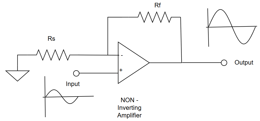
The closed-loop gain is:
[
A_V = 1 + \frac{R_F}{R_G}
]
where (R_F) is the feedback resistor and (R_G) is the resistor from the inverting input to the reference node, usually ground or mid-supply.
Key traits:
- output has the same polarity as the input;
- input impedance is very high;
- minimum gain is 1 V/V;
- ideal for sensor buffers and gain stages.
Non-Inverting Worked Example
A sensor produces (50\text{ mV}) and the ADC works best near (1.0\text{ V}).
[
A_V=\frac{1.0\text{ V}}{50\text{ mV}}=20
]
For a non-inverting amplifier:
[
20 = 1 + \frac{R_F}{R_G}
]
Choose (R_G=1\text{ k}\Omega). Then (R_F=19\text{ k}\Omega).
The output estimate is:
[
V_{OUT}=20 \times 50\text{ mV}=1.0\text{ V}
]
Voltage Follower
The voltage follower is a non-inverting amplifier with gain 1. The output connects directly to the inverting input.
[
A_V=1
]
Use it when a high-impedance signal must drive an ADC input, filter, cable, or following circuit without being loaded.
Inverting Amplifier
In an inverting amplifier, the input reaches the - input through (R_{IN}). The + input is connected to ground or a reference voltage. Feedback resistor (R_F) connects output to the - input.
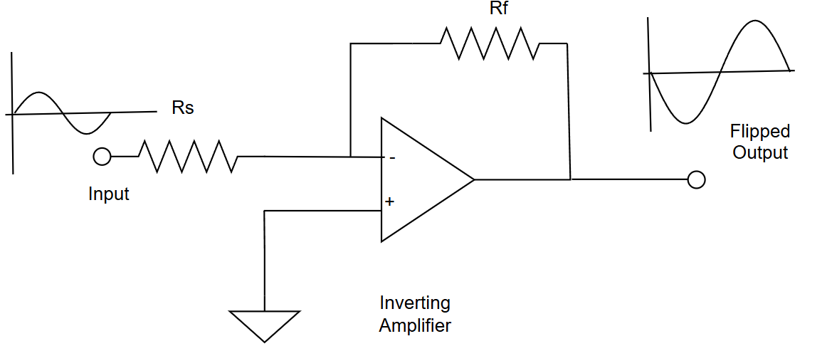
The gain is:
[
A_V=-\frac{R_F}{R_{IN}}
]
The negative sign means the output is inverted by 180 degrees. The input impedance is approximately (R_{IN}), which is useful when a defined source load is acceptable.
Inverting Worked Example
Choose (R_{IN}=2.2\text{ k}\Omega) and (R_F=22\text{ k}\Omega).
[
A_V=-\frac{22\text{ k}\Omega}{2.2\text{ k}\Omega}=-10
]
For (V_{IN}=100\text{ mV}):
[
V_{OUT}=-10 \times 100\text{ mV}=-1.0\text{ V}
]
This requires a negative output rail or a mid-supply reference. On a single 0 V to 5 V supply, a negative output is impossible unless the circuit is biased around a midpoint such as 2.5 V.
Gain-Bandwidth Check
Closed-loop gain reduces usable bandwidth. A first estimate is:
[
BW_{CL} \approx \frac{GBW}{|A_V|}
]
If (GBW=1\text{ MHz}) and (|A_V|=20):
[
BW_{CL}\approx \frac{1\text{ MHz}}{20}=50\text{ kHz}
]
This is usually enough for slow sensors but not for fast waveform measurement.
Slew-Rate Check
For a sine wave, the minimum slew rate is:
[
SR_{MIN}=2\pi f V_P
]
where (f) is frequency and (V_P) is peak output voltage. If the selected op-amp cannot meet this, the output becomes distorted even if the small-signal bandwidth looks acceptable.
Try It: Op-Amp Gain Calculator
Select the configuration, then enter any two values to calculate the third.
Choosing the Topology
| Need | Prefer |
|---|---|
| Very high input impedance | non-inverting |
| Unity-gain buffer | non-inverting follower |
| Precise input impedance | inverting |
| Weighted signal sum | inverting |
| Output same polarity | non-inverting |
| Gain below 1 magnitude | inverting |
Common Mistakes
- Forgetting the non-inverting gain has the
+1term. - Using the inverting formula with (R_G) from the non-inverting circuit.
- Designing a negative output on a single-supply op-amp without biasing.
- Choosing too much gain for the available gain-bandwidth product.
- Leaving no DC bias path for an AC-coupled input.
Summary
Non-inverting amplifiers preserve polarity, offer high input impedance, and have a minimum gain of 1. Inverting amplifiers provide precise resistor-set gain, easy summing, and phase inversion. Both must be checked against supply rails, output swing, bandwidth, slew rate, and input/output loading.
Further Reading
- Texas Instruments, "Op Amps for Everyone," chapters on inverting and non-inverting amplifiers.
- Analog Devices MT-033, "Voltage Feedback Op Amp Gain and Bandwidth."
- Microchip, "Analog Design Guide: Operational Amplifiers."